- SDC stands for Synopsys Design Constraints. It was developed by Synopsys Company.
- It is an open source file with “.sdc” as an extension.
- SDC commands are developed based on TCL (Tool Command Language) which is supported by almost all EDA tools.
- By using SDC, timing, area and power constraints are provides to the tools like synthesis, PnR and STA.
- It contains design timing information like clock definitions, generated clocks, virtual clocks, clock transitions, input port delays, output port delays, wireload model, timing exceptions and DRVs, etc…
- Following commands are the SDC constraints:
- Timing constraints:
- create_clock
- create_generated_clock
- set_clock_groups
- set_clock_latency
- set_clock_transition
- set_clock_uncertainty
- set_clock_sense
- set_propagated_clock
- set_input_delay
- set_output_delay
- set_clock_gating_check
- set_ideal_latency
- set_ideal_network
- set_ideal_transistion
- set_max_time_borrow
- set_resistance
- set_timing_derate
- set_data_check
- group_path
- set_drive
- set_load
- set_input_transition
- set_fanout_load
- Area and power constraints:
- set_max_area
- create_voltage_area
- set_level_shifter_threshold
- set_max_dynamic_power
- set_level_shifter_strategy
- set_max_leakage_power
- Design rule constraints:
- set_max_capacitance
- set_min_capacitance
- set_max_transition
- set_max_fanout
- Interface constraints:
- set_drive
- set_driving_cell
- set_input_transition
- set_load
- set_fanout_load
- set_port_fanout_number
- set_input_delay
- set_output_delay
- Specific modes and configurations constraints:
- set_case_analysis
- set_load_dc
- set_logic_zero
- set_logic_one
- Timing exceptions:
- set_false_path
- set_multi_cycle_path
- set_disable_timing
- set_max_delay*
- set_min_delay*
- Miscellaneous commands:
- set_wire_load_model
- set_wire_load_mode
- set_wire_load_selection_group
- set_wire_load_min_block_size
- set_units
- set_operating_conditions
- sdc_version
- Timing constraints:
Some of the important SDC constraints are listed below with their definitions:
sdc_version: The version of the SDC is specified through this command.
Example: set sdc_version 2.0
set_units: This command specifies the units of various parameters like capacitance, resistance, voltage, time, current and power.
Syntax:set_units-capacitance cap_unit -resistance res_unit -time time_unit -voltage voltage_unit -current current_unit -power power_unit
Example: set_units -time ns -resistance Kohm -capacitance pF -voltage V -current mA
create_clock
The command to specify the clock in the design is create_clock.
Syntax: create_clock [-name clock_name] [clock_sources] [-period value] [-waveform edge_list] [-add] [-comment].
Example1: create_clock -name “CLK1” -period 4 -waveform {0 2} [get_portsclk] (main clock comes from a particular port i.e.., source point)
Example2: create_clock -name “CLK2” -period 8 -waveform {0 4} [get_portsclk] -add (if 2 clocks are coming from same port then -add has to mention in the command). Following fig shows an example.
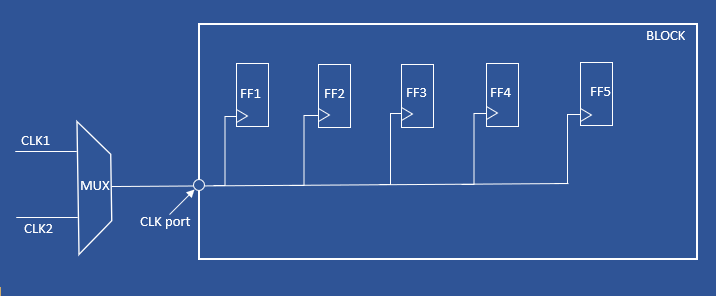
Example3: create_clock -name “VCLK” -period 10 -waveform {0 5} (Virtual Clocks will not have any source points)

Create_generated_clock
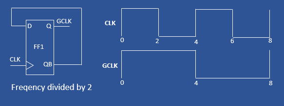
The command to specify the generated clocks in the design is “set_generated_clock”. These generated clocks are derived from main clocks in the design by using frequency dividers or frequency multipliers.
Syntax: create_generated_clock [source_objects] -source clock_source_pin [ -master_clockmaster_clock_name] [ -name generated_clock_name] [ -edges edge_list] [ -divide_by factor] [ -multiply_by factor] [ -invert ] [ -edge_shiftshift_list] [ -duty_cycle percent] [ -combinational ] [ -add ] [ -comment comment_string]
Example:create_clock -period 4 -name CLK [get_ports CLK] create_generated_clock -name GCLK -source [get_port CLK] -divide_by 2 [get_pins FF1/Q]
set_clock_transition
This command specifies the transition times of a clock or set of clocks.
Syntax: set_clock_transition [-rise ] [-fall ] [-max ] [-min ] transition_timeclock_list
Example:
- set_clock_transition -rise 0.14 -min [get_clocks CLK] #Rise transition for min operating condition.
- set_clock_transition -rise 0.21 -max [get_clocks CLK] #Rise transition for max operating condition.
- set_clock_transition -fall 0.2 [get_clocks CLK] #Fall transition for min and max conditions.
- set_clock_transition 0.11 [all_clocks] #same transition value reflects for all rise, fall, min and max.
set_clock_latency
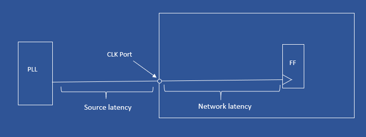
Latency means the amount of time taken by the clock to reach from clock port to clock pin of sequential element. There are two latency components, source latency and network latency. To specify source latency “-source” switch has to mention in the command.
Syntax: set_clock_latency- rise ] [- fall ] [- min ] [- max ] [- source ] [- late ] [- early ] [- clock clock_list] delay object_list
Example:
- set_clock_latency -source -early 0.3 [get_clocks CLK] #Source latency for shortest path.
- set_clock_latency -source -late 0.8 [get_clocks CLK] #Source latency for longest path.
- set_clock_latency 0.5 [get_clocks CLK] #Network latency
set_clock_uncertainty
For ideal clocks, clock edges are arrives time. But for real clocks, there may a variation in arrival of clock edges. For example, consider a clock with 1ns time period, for ideal clock rise edge come at 0ns and fall edge comes at 0.5ns and again rise edge comes at 1ns. For real clock, there may be variation like rise edge come at 0.02ns and fall edge comes at 0.54ns and again rise edge comes at 1ns. This happens because of clock skew, crosstalk and OCV. This will affect the timing, to model this variation clock uncertainty using.

Uncertainty classified into two types: Intraclock uncertainty and Interclock uncertainty.
- Intraclock uncertainty: Clock skew can be between different points of the same clock
- Interclock uncertainty:Clock skew can be between different clocks.
- Syntax: set_clock_uncertainty [-from | -rise_from | -fall_fromfrom_clock] [-to |-rise_to | -fall_toto_clock] [-setup ] [-hold ] [-rise ] [-fall ] [object_list] Uncertainty_value
- Example:
- set_clock _uncertainty 0 . 5 [get_clocks CLK] #Intraclock uncertainty for both setup and hold
- set_clock_uncertainty -setup 0 . 5 [get_clocks CLK] #Intraclock uncertainty for setup
- set_clock_uncertainty -hold 0 . 2 [get_clocks CLK] #Intraclock uncertainty for hold
- set_clock_uncertainty -from CLK1 -to CLK2 -setup 0.6 #Interclock uncertainty for setup
- set_clock_uncertainty -from CLK1 -to CLK2 -hold 0.9 #Interclock uncertainty for hold
set_input_delay
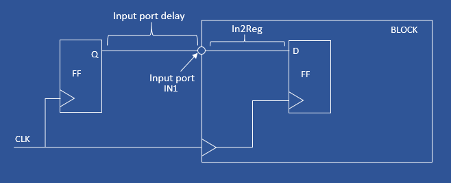
This command specifies the data arrival timings relative to the clock indicated by the “-clock” option at the selected input port.If input delay not specified then tool considers that input delay is zero and uses entire clock to model the in2Reg timing path.
Syntax:set_input_delay [ -clock clock_name] [ -clock_ fall ] [ -level_sensitive ] [ -rise ] [ -fall ] [ -max ] [ -min ] [ -add_delay ] [ -network_latency_included ] [ -source_latency_included ] delay_valueport_pin_list
Example:
-
-
- set_input_delay -clock CLK 1.5 [get_ports IN1] #input port IN1 delay
- set_input_delay -clock CLK1 2.0 [all_inputs] #same delay for all input ports
-
set_output_delay
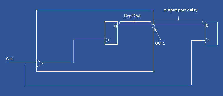
This command specifies the data required timings relative to the clock indicated by the “-clock” option at the selected output port.If input delay not specified then tool considers that input delay is zero and uses entire clock to model the Reg2Out timing path.
Syntax:set_output_delay [ -clock clock_name] [ -clock_ fall ] [ -level_sensitive ] [ -rise ] [ -fall ] [ -max ] [ -min ] [ -add_delay ] [ -network_latency_included ] [ -source_latency_included ] delay_valueport_pin_list
Example:
-
-
- set_output_delay-clock CLK 2.5 [get_ports OUT1] #output port OUT1 delay
- set_input_delay -clock CLK1 2.2 [all_outputs] #same delay for all output ports
-
set_false_path
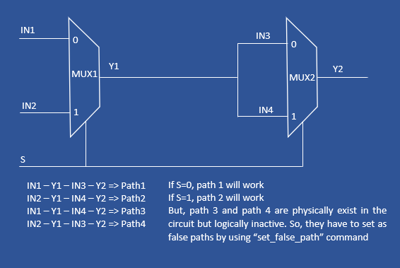
The paths which are physically existing in the design but logically inactive in the functionality in the chip, those paths are considered as false path. For false paths, there is no need to calculate timing. Those kinds of paths are specified by using set_false_path command.
Syntax:set_false_path [- setup ] [- hold ] [- rise ] [- fall ] [- from from_list] [- to to_list] [- through through_list] [- rise _from rise_from_list][- rise_torise_to_list] [- rise_throughrise_through_list] [- fall_fromfall_from_list] [- fall_tofall_to_list] [- fall_throughfall_through_list] [- comment comment_string]
Example:
-
-
- set_false_path -from {FF1} -to {FF2}
- set_false_path -from [get_clocks {my_clk}] -to [get_clocks {test_clk}]
-
set_multicycle_path
By default, all paths are single cycle paths means the data launched at current active clock edge should receive at immediate next clock edge. But, depending ondesigners requirements some of the path require more than one clock cycle to capture data reliably (to meet setup and hold timings). So, those path which require more than one clock cycle are considered as multicycle paths and specified as multicycle paths using “set_multicycle_path”.
Syntax: set_multicycle_path [ -setup ] [ -hold ] [ -rise ] [ -fall ] [ -start ] [ -end ] [ -from from_list] [ -to to_list] [ -through through_list] [ -rise_fromrise_from_list] [ -rise_torise_to_list] [ -rise_throughrise_through_list] [ -fall_fromfall_from_list] [ -fall_tofall_to_list] [ -fall_throughfall_through_list] path_multiplier [ -comment comment_string]
Example:
-
-
- set_multicycle_path 2 -from ff1/Q -to ff2/D
-
set_max_delay
This command specifies the maximum delay on timing path. For example, a required maximum delay is 6ns then it can be specified by using set_max_delay.
Syntax:set_max_delay [ -rise ] [ -fall ] [ -from from_list] [ -to to_list] [ -through through_list] [ -rise_fromrise_from_list] [ -rise_torise_to_list] [ -rise_throughrise_through_list] [ -fall_fromfall_from_list] [ -fall_tofall_to_list] [ -fall_throughfall_through_list] delay_value [ -comment comment_string]
Example:set_max_delay -from [get_ports IN1] -to [get_ports OUT1] 6.0
set_min_delay
This command specifies the minimum delay on timing path. For example, a required minimum delay is 3ns then it can be specified by using set_min_delay.
Syntax:set_min_delay [ -rise ] [ -fall ] [ -from from_list] [ -to to_list] [ -through through_list] [ -rise_fromrise_from_list] [ -rise_torise_to_list] [ -rise_throughrise_through_list] [ -fall_fromfall_from_list] [ -fall_tofall_to_list] [ -fall_throughfall_through_list] delay_value [ -comment comment_string]
Example:set_min_delay -from ff1/Q -to ff2/D 3.0
set_max_fanout
This command specifies the maximum fanout for a pin or port in the design.
Syntax: set_max_fanoutfanout_valueobject_list
Example: set_max_fanout 16 [current_design] #All pins fanout will be 16
set_max_transition
It is the maximum time taken to change logic from 0 to 1 or 1 to 0.
Syntax: set_max_transitiontransition_value [-data_path] [-clock_path] [-rise] [-fall]object_list
Example: set_max_transition 0.2 UCLKDIV0/QN
set_max_capacitance
This command specifies the maximum capacitance for an output pin of a cell.
Syntax: set_max_capacitance value object_list
Example: set_max_capacitance 0.2 [current_design]

