
Placement is the process of placing of all standard cells that are present in netlist by the tool into the core area.Tool also optimizes the design while placing. During placement trail routing also can be done by the tool. Placement can be done by the tool in 3 different techniques, which are
- Timing driven placement – Placement happens with timing as a priority
- Congestion driven placement – Placement happens with routing as a priority
- Power driven placement – Placement happens with power as a priority
Goals of placement
- Timing, area and power optimization
- Minimize congestion and congestion hotspots
- Minimum cell density, pin density
- No timing DRV’s
Inputs of placement
- Netlist
- Physical libraries (.lef)
- Floorplan DEF file
- MMMC (Multi Mode Multi Corner)
- Timing libraries (.lib)
- RC corners
- SDC file
- UPF file (if the design has multiple voltage domains)
Checks before placement
- Netlist should be clean.
- Floorplan DEF should be good
- Proper Pin placement
- Macros and pre-placed cells should be in fix.
- Power routes should be free of DRCs
- Check for don’t use, don’t touch cells and routes should be applied properly.
Placement steps
Placement has many steps, so, let us divide all the steps into 3 parts:
Preplacement
⇓
Placement
⇓
Post placement
Pre-placement
- During this step all the pre-placement checks have to do.
- If everything is clean then all the required pre-placement cellshave to place (Like Endcap, Well Tap, Spare cells, Decap cells etc.…).
Note: We have already explained all pre-place cells in Physical only cells topic.
Placement
Now, during placement mainly 3 steps can be done, which are discussed below:
- Global placement
- Early global routing
- Legalization
- High Fanout Net Synthesis (HFNS)
- Scan chain reordering
Global Placement
During global placement, tool places all the standard cells into the core area. As you read already in the placement definition, tool follows different types of techniques to place standard cells into the core area. In this step, tool will not follow any DRCs (like standard cells overlapping, miss alignment to the std cell rows) and creates more density areas following figure shows the global placement. Trail routing also can be done by the tool after one global placement iteration.

Trail Routing or Early Global routing
During placement stage tool do trail route along with placement of standard cells.During trail routing tool divides entire metal layer into number of GCells. Each GCell carries set of horizontal & vertical routing tracks following figure shows the example of GCells. By using those GCells tool do quick routing to estimate routing related congestion and net parasitic (resistance and capacitance) values for optimization and timing analysis.

In the above figure you can see a vertical metal layer. Entire layer can be divided into 16 GCells and each GCell have 5 routing tracks.
What is congestion?
When the number of routing tracks available for routing in a given location is less than the number necessary, the area is considered congested and hence, it is termed as routing congestion.
Congestion=Available routing tracks – Required routing tracks
Note: The result should be 0 (zero) or greater than 0(zero). If you are getting negative value that means you have congestion.
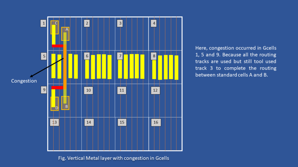
In the above figure you can see congestion occurred in metal track 3. Where that track is already used to connect standard cells C and D from that same track another route is connected to A and B. So, here tool used already routed track to complete the routing. Hence congestion occurs .Trail routing almost meets 95% of final routing criteria. After trail routing completed, if the congestion is in acceptable range then we can proceed to next step. Usually acceptable congestion value is 0.2% without hotspots. Here, hotspots mean if all the neighboring Gcells are congested then it is called as hotspot.
Legalization
During legalization tool tries to spread the standard cells. If the cell density is more in a particular area in order to get rid of power issues, tool will distributes the cells. In this step the tool exactly aligns all the overlapped standard cells into standard cell rows by following DRC rules and it makes sure that there are no standard cells placed out of the core area. The following figure shows after legalization step performed by the tool.

High Fanout Net Synthesis
Some of the nets will have very high number of fanouts like Reset, Scan Enable etc… But, there is a restriction for maximum fanout in timing constrains.Even though it is a soft constraint high fanout will increase load capacitance. Based on the fanout constraints tool identifies the high fanout nets in the design. Then tool optimizes these nets by picking the right drivers or adding buffers to drive the load, adding repeaters to reduce on delay and signal integrity, and balancing the net’s capacitance and resistance to strengthen the signal integrity. By doing optimization tool meet the signal quality and timing requirements of the design while minimizing delay, power consumption, and noise on high fanout nets. Following figure shows an example for HFNS.

Let’s consider the max fanout constraint is ‘7’ for this design. But in the above figure before HFNS, on the RESET port have 21 fanout, so, tool identifies this reset port net and do optimization by buffering. So, tool added 3 buffers and at each buffer output tool connected 7 cells to meet the fanout constraint.
Scan chain reordering
During the DFT stage, all the flipflops are connects in the form of shift registers pattern like the circuit shown in below image.
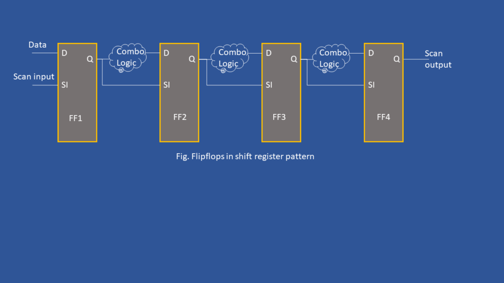
DFT team create multiple scan chains like the diagram shown above. They divide all available flipflops in the design into equal number of sets and stitches scan chain. Each set represents one scan chain. For example, consider a design have 12 flipflops then DFT team creates 3 scan chains, each chain will contain 4 flops and all are connected to each other in shift registers pattern.
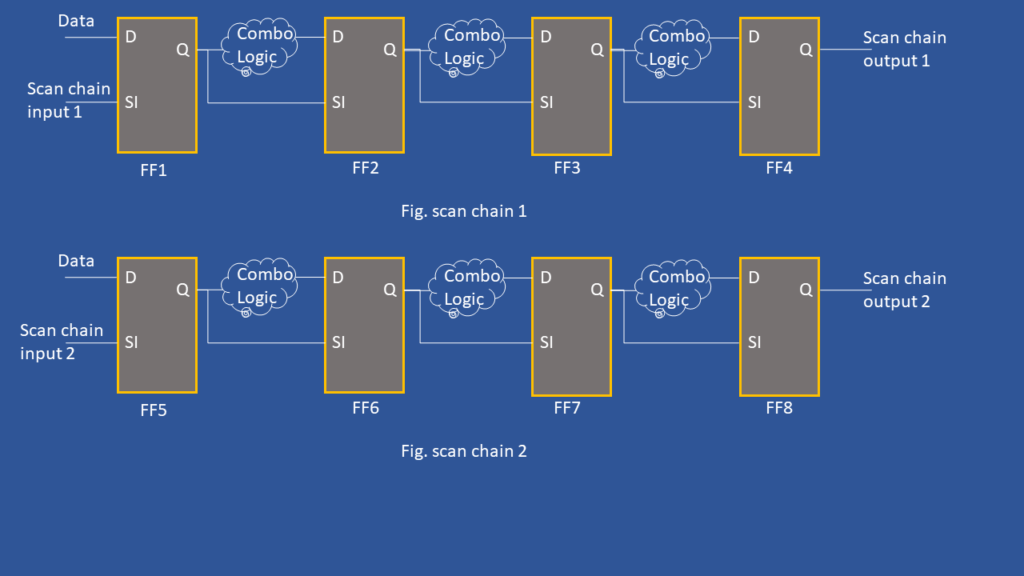
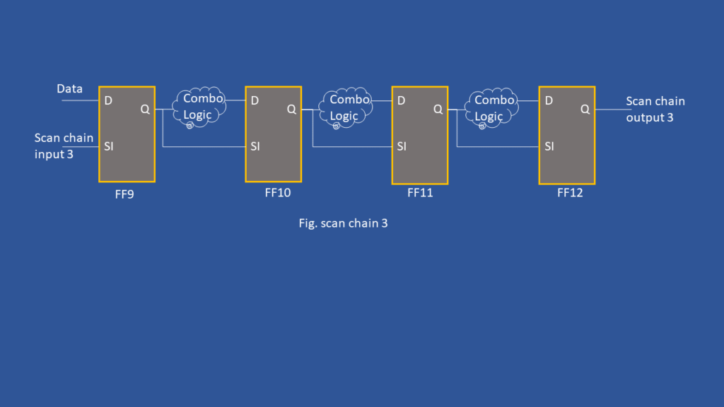
After placement, all the flipflops are placed into core area and there will be some distance in between the flops. to complete routing below figure shows an example.
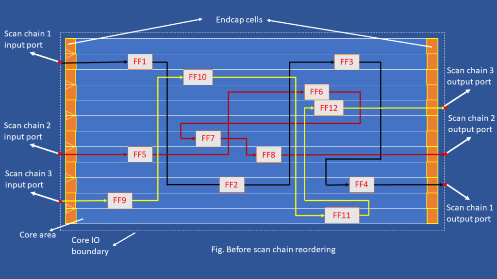
So, which scan chain reordering tool deletes all existing scan chain routes and creates a fresh scan chain routes by connecting the flops which are near to each other. There is no requirement to check the flops are functionally talking or not for scan chains.
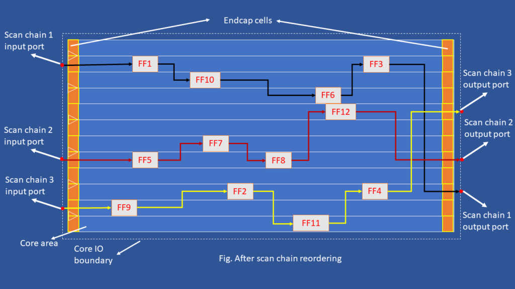
Note: functional routes are not like scan chain, for functional routes FF1 output have to must connect input of FF2, FF2 output to FF3 input and go on.
Post placement
- During post placement tool tries to meet all design timing requirements like DRVs then WNS (Worst Negative Slack) and TNS (Total Negative Slack) only for setup slack.
- Finally tie cells also can be placed by the tool for the required input pins.

Excellent
Thanks for the comment
Informative
Thanks for the comment.
i have a doubt in placement stage can we run place_opt command multiple times
Yes, you can.
Hii VLSI TALKS,
how can we reduce the timing issues in Placement Stage
Vt swapping, cell sizing, path grouping, buffer and inverter pair insertion
What are the types of routing carried out by the tool in the placement stage in the global routing
As we do power routings in between floorplan and placement stages. So, at placement stage tool routes both signal nets and clock nets. Tool won’t touch power nets.
Thank you
Timing fixes at Placement stage
Mostly we do path grouping for timing fixes or if violation because of net length we have to create bounds or need pull cells by using magnetic placement
explain about congestion and timing fix in placement stage?
Congestion: We have to use cell padding, partial blockage, should avoid notches while placing macros
Timing: Mostly we do path grouping for timing fixes or if violation because of net length we have to create bounds or need pull cells by using magnetic placement
Where can I find physical only cells topic
Hi sunny, we are working on these topics. will upload soon…
What are the timing optimization techniques in placement and group path?
Here, group path is one of the technique to fix timing.
1) Check floorplan, proper placement of macros, apply blockages properly, etc… (Check floorplan guidelines)
2) Buffering
3) Cell sizing
4) VT swapping
5) Group path
what does mean routes should be applied? what exactly routes here?
At placement stage, global routing have to do, which creates routing for entire design which meets almost 90% to 95% for actual routing. By using these global routes tool calculates timing, congestion.
Good Information
Thank you so much for your kind words! I’m glad to know the content has been helpful—your support motivates me to keep sharing more valuable information!
Can i have some useful app options used in place/cts/route stages
App options we can’t say that selective options are best like that, based on the requirements app options have set…
Thank you, this website is amazing.
Where can I find the explanation about the pre-placement cells (endcap, well tap, spare cells etc..) couldn’t find it. thanks in advanced.
Thank you so much for your kind words! I’m glad to know the content has been helpful—your support motivates me to keep sharing more valuable information!. We haven’t posted about pre-placement cells, we are working on the left over topics and will post soon…
Nice explanation sir
Thank you so much for your kind words! I’m glad to know the content has been helpful—your support motivates me to keep sharing more valuable information!
Post Placement also means place_opt? If not which stage will be place_opt stage?
Post placement and place_opt both are same
thats great post thanks
Thank you so much for your kind words! I’m glad to know the content has been helpful—your support motivates me to keep sharing more valuable information!
Where is the physical only cells topic?