What is Floorplan?
Floorplan is simply the planning of where things will be placed in an orderly manner.In simple words its similar to house construction,when you are planning to construct a house first we need a plan right! similary In PD also we need floorplan.
- Floorplan is the major stage in the PnR flow. It will decide how good your design. A good floorplan gives better PPA (Power, Performance and Area).
- Floorplanning is the process of creating core area, specifying core to I/O boundary spacing, standard cell rows, placing I/O pins, placing macros using macro guidelines and adding placement blockages and halo. So, during this stage above things have to do to avail better area to place standard cells in the core area, to avoid congestion and to avoid IR drop.
Types of designs
There are two types of designs
1) Core limited design
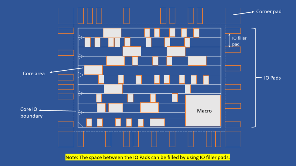
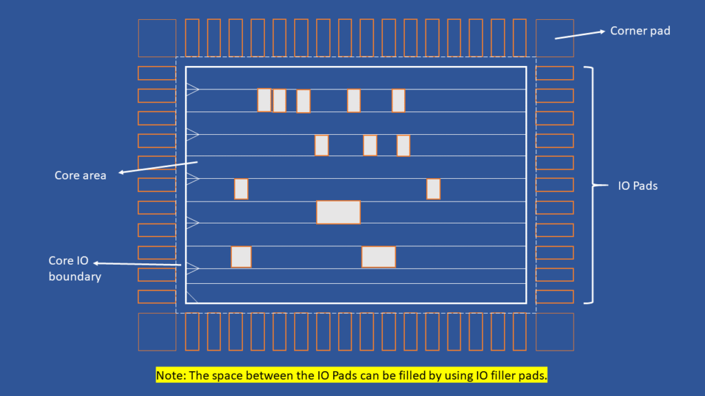
2) Pad limited design
Core limited design: The size of the die is restricted by the core’s area. Possible lower number of IO pads.

Pad limited design: The size of the die is restricted by the Pad area. Core area is dominated by the Pad area.

To start floorplan first of all, required input files have to load into the PnR tool. Following mentioned files are required input files to start floorplan:
Importing input files
- Netlist (.v)
- Physical libraries (.lef) – Tech LEF & Standard cell LEF
- MMMC
- Timing libraries (.lib)
- RC Coefficient files
- SDC
- UPF (Unified Power Format) – (Optional)
- Floorplan DEF (Optional)
Note:LEF files must be loaded first during import, followed by LIB files.
Sanity checks
All imported input files should be clean,accurate and data should match among them. So, to check the quality of input files, sanity checks have to perform. If everything is good with the input files then we proceed to next stage, otherwise we have to sort out the issues with the files and fix those issues to move forward to further stages.
Sanity checks to perform on input files are listed below:
Design checks
This sanity check have to perform on Netlist to check whether the netlist is free of design issues or not. Some of Design issues are listed below:
- Combinational loops
- Floating inputs
- Multi driven inputs
- Un intended latches
- Tri stateable gates
- Empty modules in netlist
- Assign statements
Innovus tool command for design check is “checkDesign -netlist”
Library checks
This sanity check have to perform to check correlation between the Netlist and libraries. The cells present in the netlist should be present in the libraries (timing and standard cell libraries).
Innovus tool command for library checks is “checkDeisgn -physicalLibrary” and “checkDeisgn -timingLibrary”.
Timing checks
This sanity check is to check quality of SDC file, which means each and every path in the design should be constrained. If any path is not constrained then those paths are considered as unconstrained timing paths. And also it checks the consistency among the constraints.
Innovus tool command for timing check is “check_timing”.
Floorplan control parameters
Before doing floorplan implementation in tool, you should understand some parameters which are helpful to do a good floorplan.
Core area: Core area is part of the Die (Full chip) where all type of cells (like standard cells, macros, blockages, physical only cells) can be placed. All types of cells must be place only inside the core area.
core size=(Standard cell area+Macro area+Blockages area)/(Standard cell utilization)
Aspect Ratio: Aspect ratio is the difference between the height of the core and width of the core. For square core area, aspect ratio is 1.0. If the aspect ratio is 0.5, then the width of the core is 2 times of height. Similarly, if the aspect ratio is 2.0, then the height of the core is 2 time of the width.
Aspect ratio=(Height of the core area)/(width of the core area)
or
Aspect ratio=(Horizontal routing tracks)/(Vertical routing tracks)
Here, height of the core area is the multiple of horizontal routing tracks. Similarly, width of the core area is the multiple of vertical routing tracks.
Routing tracks
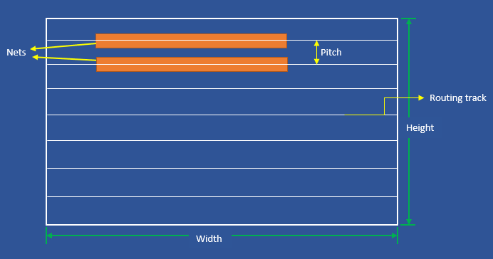
Entire metal layer can be divided into number of horizontal and vertical lines, each line can be considered as one routing track. These tracks are virtual, created for routing purpose (physically don’t exist in the design). A net or route middle is exactly aligned automatically to the routing track like shown in the below picture. The distance between the tracks is termed as pitch.

Utilization
Utilization means the area occupied by the standard cells, macros and blockages in the core area. Usually, it is specified in percentage.It is assumed that Standard Cells occupy 70% of Base Layers and that Routing uses the remaining 30%. Utilization may be adjusted in accordance with the size of the macros
Utilizaton=(Standard cell area+Macro area)/(Total core area) x 100
Manufacturing Grid
It is the minimum area that can be manufacturable by the foundry for your technology node. It is defined in technology LEF file. (ex: 0.005)
Standard cell site
It’s a minimum width and height of cell that can occupy in the core area. All the cells in the core area will be the multiples of standard cell sites. A least occupied standard cell site is the filler cell that can occupy only one standard cell site.
Standard cell rows
Standard cell rows are created in core area to place standard cells. During the placement stage all the standard cells in core area will have to align with in these rows.
By seen the below figure you can understand that every standard cell height is fixed but width may varies
Inverted Row
You can seen in the figure that every standard cell row has VDD & VSS. While coming to second row its inverted i.e VSS & VDD. Its because the first row cells and second row cells can share the same VSS so that more area is saved.If its doesn’t follow inverted row concept huge area will be wasted.

Note:In general, notch represents the VSS or bottom of the standard cell.
Macro Guidelines
Macro is also like a standard cell but gigantic in size. macros are like some other design is using as a part of current design, it can be altered, logic fixed for the macros. These are available in different shapes (rectangular, square) and sizes, some of the macro shapes are rectilinear (some of the macro shapes are like a night mare for many physical design engineers).
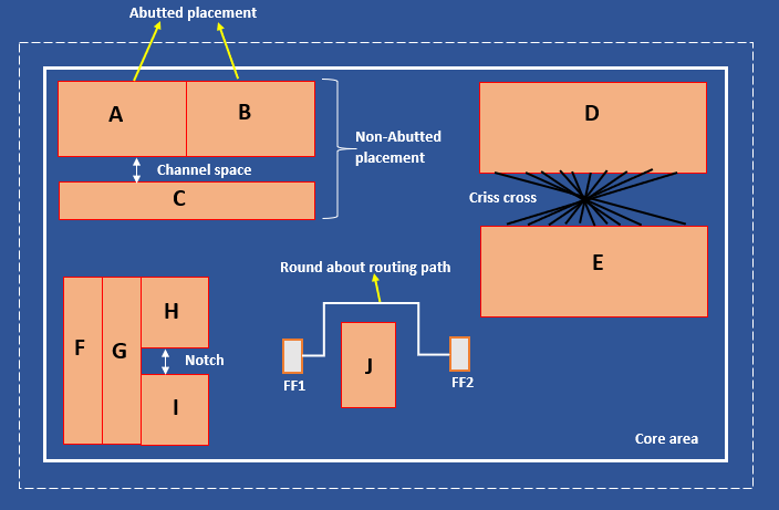
• Macros should be place at periphery of the core boundary.
• Macro pins should be face towards the center of the core area.
• Macros should not place at middle of the core area. If it places middle of the core it will create round about routing paths.
• Avoid notches in the core area.
• Avoid criss-cross.
• Place talking Marcos near to each other.
• Maintain proper halo around the macros.

Types of placement blockages
There are 3 types of placement blockages, which are:
• Hard blockage
• Soft blockage
• Partial blockage
Hard blockage: It will not allow to place any type of standard cells inside the blockage area.
Soft blockage: It will allow only buffers and inverters inside the blockage area while optimization.
Partial blockage: It will allow any type of standard cells inside the blockage but there is a hard rule that it will allow only for some percentage of area. For instance, consider partial blockage of 30%, means tool allows 30% percentage of blockage area to place standard cells.
Halo: There is another type of blockage which is “Halo”. Halo is nothing but hard blockage, which is placed around the macros. Here, difference between the halo and hard blockage is halo will move along with the macros. But hard blockage will not move along with macros.
Types of floorplans
There are three types of floorplan techniques:
• Abutted floorplan
• Non-Abutted floorplan
• Mixed floorplan
Abutted floorplan type: For this technique, no spacing can be maintained between the elements in the floorplan (Zero channel spacing among the macros).
Non-Abutted floorplan type: For this technique, some spacing can be maintained among the elements in the floorplan.
Mixed floorplan type: For this technique, name of type itself explaining that combination of both Abutted and Non-Abutted type floorplan techniques. There will be some spacing for few elements and no spacing for few elements.
Outputs
- Floorplan DEF
• Macro placement info
• Core boundary and area
• Pin positions
• Placement and routing blockages positions


Is aspect ratio the difference between height of the core area and width of the core area or the ratio between height of the core area and width of the core area?
simple, height by width
What is the aspect ratio for irregular shape block. Is there any formula?
No change, the same formula can be applied for rectilinear shapes also…
Can you please elaborate the how will you do?
Hello Charan,
Aspect ratio is same for both normal and rectilinear blocks. Because aspect ratio is (core height/core width). So even though the block have the cuts to calculate we have to consider the (max core height/max core width) after the cut.
What are the checks we do before and after floorplan in ICC ll compiler?
Hello Pravallika,
Floorplan checks are the same irrespective of the tool.
can you include the commands that are used in every stage (from floorplan to routing) with an explanation, as you did in the synthesis
like famous tool commands like icc2
We are working on it…
why LEF files must be loaded first? Can you please elabarate ?
Because lef files will have abstract rules like standard cells width, height, and metal layers info and all. So, design need to be load with lef files during PnR implementation…
PLEASE IM CLARIFICATION IF IM WORNG CORRECT ME …
HALO :- IS IT ALLOW BUFER AND INVERTER INSIDE DURING OPTIMIZATION NOTHING BUT SOFT BLOCKAGES..??
Halo is purely hard blockage. It won’t allow any kind of standard cells
How to calculate aspect ratio according to macro count? and vise versa.. how do we estimate number of macros according to die size?
1)For example, if you have a chip with 10 macros, and its width is 5 mm and height is 2 mm, the aspect ratio would be 2/5 = 0.4.
2) For example, if you have a die with an area of 10mmsquare and each macro occupies an area of 1mmsquare, then you could estimate that you could fit approximately 10 macros onto the die.
Can you explain what is a blockage actually is?
how to check macros palced properly or not according to macro guidlines after floorplan
You have to check manually for the placement of macros. Even if you find all macro placements are fine, you may see issues in later stages like placement (ex:Congestion).