What is routing
Routing is the process of creating physical connections between or among the signal pins by following DRC rules and also after routing timing (setup and hold) have to meet.
Types of routing
Usually there are three types of routings available which are mentioned below:
- Pre-routing – also known as power routing which comes under power planning
- Clock routing – it can be done while building clock tree in CTS stage
- Signal routing – it is the stage after CTS.
Goals of routing
- Minimize the total interconnect or wire length and vias.
- Complete the routing within the area of the design.
- No DRC violations.
- Meeting the timing and
- No LVS (Layout Vs Schematic) errors.
Inputs of routing
- Netlist and CTS DEF
- Timing libraries and Physical libraries
- Tech LEF
- CapTables or QRC tech file
- SDC
Tasks perform by the signal routing
While doing signal routing tool follows 4 steps. They are:
- Global routing
- Track assignment
- Detailed Routing
- Search and repair
Global routing
Global routing was already discussed in placement stage as early global routing or trail routing. During the global routing tool removes all existing routing and do trail routing again with out following any DRCs.
In this stage, tool divides entire core area into global cells (gcells) and tries to find the shortest path from pin to pin as per the logical connectivity to route using the gcells. If you want to know about gcells then please refer early global routing in placement page. While doing global routing tool tries to avoid routing over the routing blockages, and never touches the pre-routes (power planning) and CTS nets.
Tool do global routing majorly by using two algorithms. They are:
- Maze algorithm
- Steiner Tree algorithm
Maze algorithm
- It is most widely using algorithm to find the shortest path between two points.
- For example, consider two cells i.e.., cell1 and cell2. Cell1 output connects to the cell2 input.
- This could be done in 3 steps:
- To identify the ‘Source’ and ‘Target’ pins for cell1 and cell2 and create Routing grid.
- Based on the distance of wave-front, from ‘S’, the adjacent grid boxes are progressively filled till it hits target node ‘T’
- The shortest and the least detoured path is back-traced from ‘T’ to ‘S’
- Maze Algorithm guarantees there is exists a valid path and it’s the shortest path.

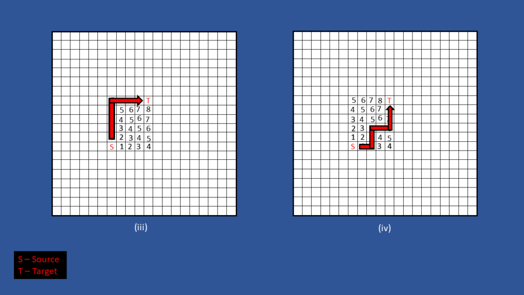
If you see above example, tool found all possible ways to do routing from Source to Target, then it will sort out the shortest way and completes the routing in that path.
Steiner tree algorithm
- A rectilinear Steiner tree is used for routing because it minimizes the total length of wire.
- If a net has one source point and more than one target points then Steiner tree algorithm is used.
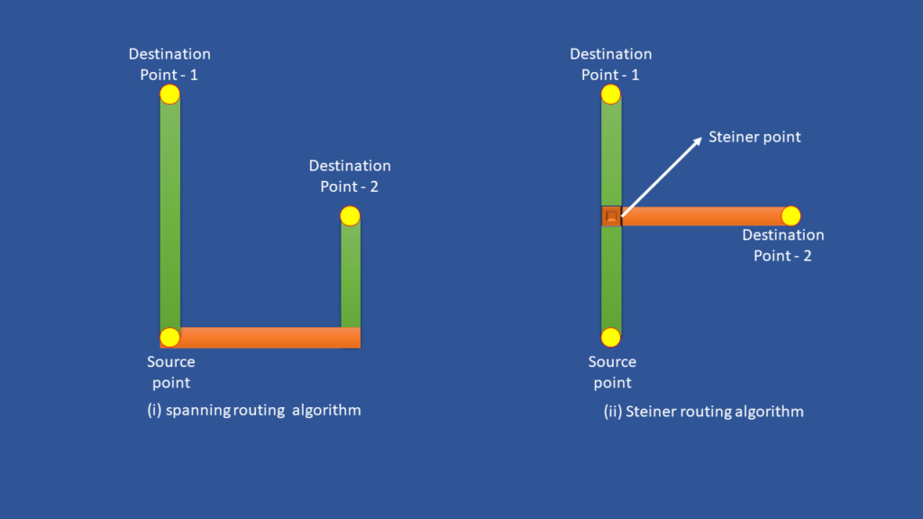
- In the above example, there are three pins (one source and two sinks).
- In fig(i), spanning algorithm is used. This is more wire length it is used in the initial stages.
- But in fig(b), Steiner tree algorithm is used which made a common wire for some distance to reduce the wire length.
Track assignment
During this stage, tool replaces the global routes with actual metals, and those actual metals have to follow DRC rules. Then now those actual metals will get real DRC violations, signal integrity (SI) and timing violations. Those violations are fixed in the succeeding stages.
The main tasks performed by this stage are,
- Assigning real metal in horizontal and vertical partitions.
- Rerouting all overlapped wires.
Detailed routing
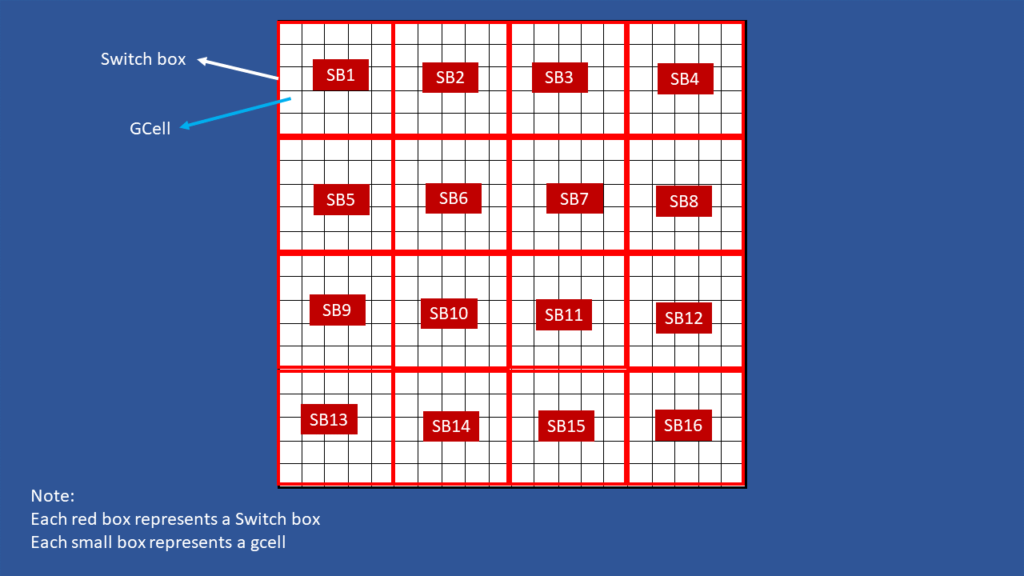
This is the final stage of routing of the design and this can be done after CTS stage. During this stage, tool takes care of routing and completes the routing without leaving DRC violations and also improves the signal integrity (SI). While doing detail routing, tool divides entire block into multiple switch boxes or Sboxes. Each switch box will carry multiple gcells. The switch boxes boundaries are align to the gcells. The following figure shows the example of switch boxes
Search and Repair
This stage is the part of the detailed routing, but search and repair starts after first iteration of detailed routing. During this stage, all shorts and spacing violations are identified and resolved by the tool.
Post routing
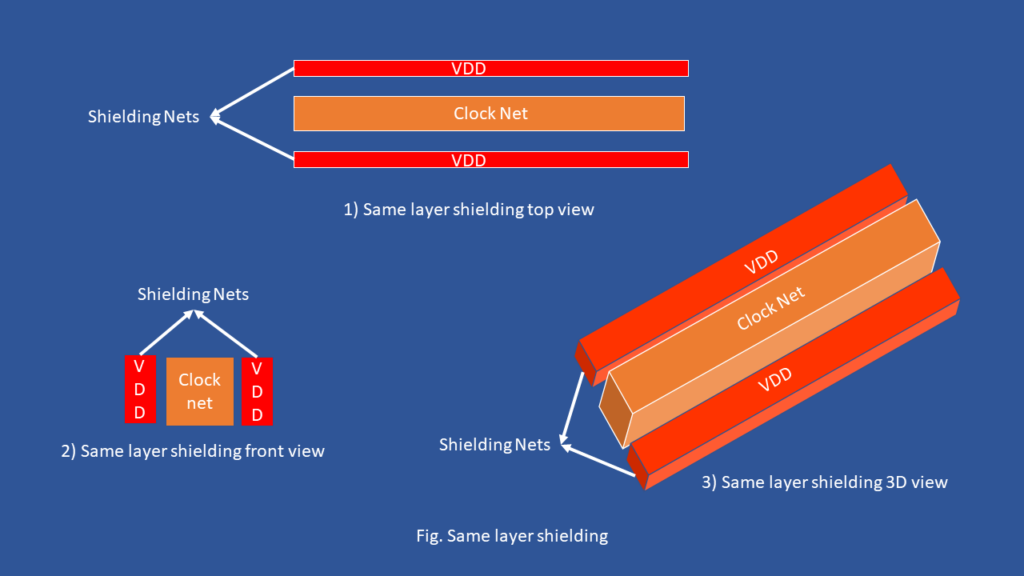
- Signal Integrity (SI) Optimization by NDRs and Shielding for the sensitive nets.
- Types of Shielding for sensitive nets
- Same layer shielding
- Adjacent layer/ Coaxial shielding

Fill stage
- In this stage, fillers are added:
- Filler cells
- Metal fills
Outputs
- GDS file
- Routing DEF file with no opens & shorts
- Timing & Congestion report
- SPEF
- SDC

How can we fix cap violations manually after postroute
At ECO stage, splitting fanout by breaking net and add buffer, sizing. By using these techniques we can fix cap violation…
Why are Metal fills added ?
Metal fills are added to reach the metal density requirements, which is done to avoid the issues in manufacturing.
can you briefly explain about the filler stage?